
Tailfeathers
Elevators
Rudder
Stabilisers
Gear legs
|
|
The tail control surface bushings are driven out using a drift. The same drift will safely insert the new ones. |
 |
Trim mechanism, ready for disassembly |
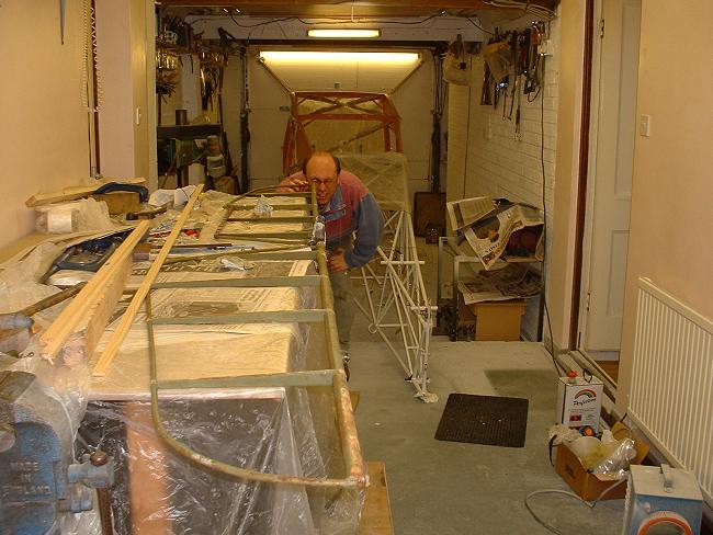 |
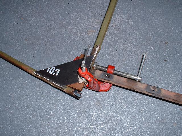
Andy assists with the set-up and alignment of the elevators. All tubes and ribs were bent, so after straightening, the horn bolt holes will be redrilled. |
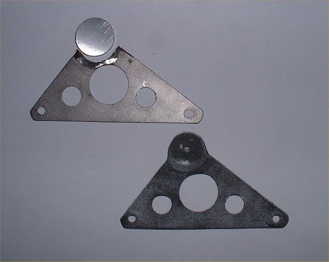 |
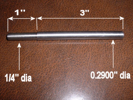
During this process, the trim bellcrank is reworked (see elevator trim system in original condition). The two extreme holes have been punched and then reamed back to correct size (thanks to Forrest for the tip). The existing central boss containing the pivot hole is constructed using two reinforcing plates welded either side of the main plate. In mine, punching wouldn't work because of the small gap between the plates, so I cut the whole thing off and made a 1" diameter 3/16" thick button to weld in. The faces were even precision ground, but with it to be welded in, this was probably overkill! The photo shows the as-yet-not-welded button, and the bellcrank sits on a photocopy so that I drill the hole in the right place! |
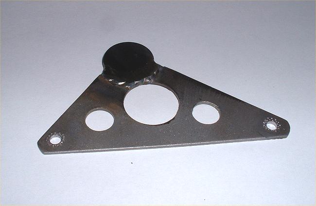 |
And here it is welded in, I have yet to drill
and ream the 3/16" diameter hole. Have you seen my new bronze trim screw and stainless barrel (on the right)? Thanks, David, for your excellent machining skills. All these changes and new parts and re-sizing of holes (including those on the actuating arms) gets rid of every ounce of trim tab slop! |
 |
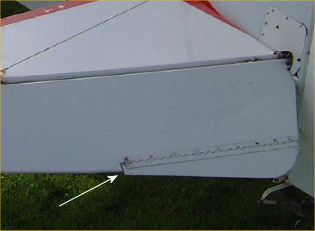 |
The cut-out for the pitch trim tab in the left elevator was always out of kilter...the trim tab stuck out about 3/4" from the trailing edge of the elevator, and the left elevator was a different size& shape to the right... |
 |
 |
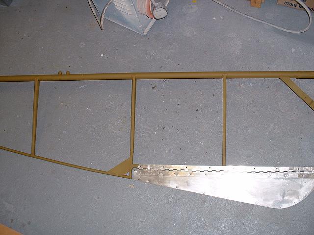 |
...and required the repair of another previous repair to put right. This necessitated moving the trailing edge tube 3/4 inch aft so that the line of the trailing edge matched the aft line of the trim tab. My finished repairs are untidy, but only because of the attempts by persons unknown years ago to do a bodge job. Should look alright under fabric. At least it is structurally OK. |
 |
The two elevators and a rudder hang up to dry. The white epoxy primer was tinted with a little bit of black, to make grey, so that on those items requiring a top coat in white, I can see where the paint has been applied... |
 |
...and those bits that will not be hidden by fabric I have top-coated. As well as the hinge points, the rudder horn on the rudder gas also been top-coated. |
 |
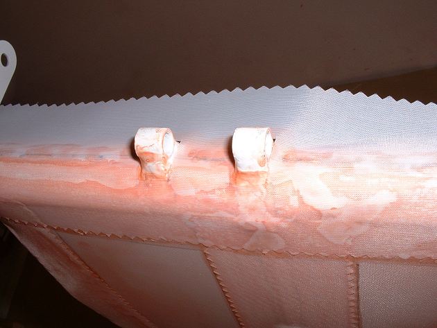
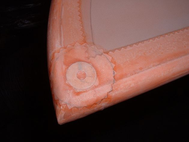
A small aluminium fairing (under the small fabric patch) is used to lift the fabric slightly adjacent to the trim tab system, so as to increase the clearance between the mechanism and the fabric. |
 |
Inspection rings are glued (and later covered with a doily) where access will be required for maintenance & lubrication of the trim bellcrank. The black masking on the trim actuating arm will be removed after spraying. |
 |
 |
 |
All the reinforcing tapes along the spines of all the control surfaces were prepared and fixed in accordance with these three photos. A small application of pink goo prevents the cut-outs from unravelling. |
 |
 |
I am using Light bias tape for the curved
portions. A pencil line is drawn down the spine of both the rudder and the tape, and
then the tape is attached only along the spine, with a little tension to start the laying
of the tape flat on each side. After this thin line is dry, each side can then be laid flat with the application of the Poly-Brush. No further heat shrinking required. |
 |
Here is the finished result...not too much "shrinking" of the tape because I did not pull too much on the tape for the shape. The thin weave of the Light tape lays flat on the sides nicely. |
 |
Stabiliser etch primed after blasting......and then epoxy primed. |  |
NOTE: you must provide a mechanical key (by sanding) to the etch prime if overcoating with the epoxy more than 12 hours later. |
 |
But what's this? My saucepan holder is back in the kitchen... |  |
...in fact I am drilling the holes for mounting the stabilisers to the fuselage stubs (which were welded up a long time ago because they were so out of shape. I need to do this now before spraying of the fuselage starts. |
 |
 |
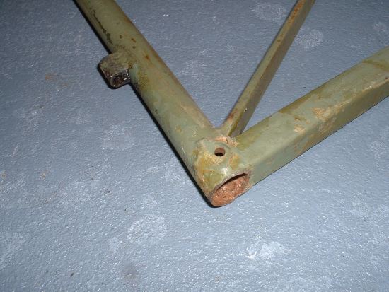
The two pictures here show the original holes that I welded up due to elongation. | |
 |
I use the stabiliser jig that I made some time ago, to ensure that the elevator hinge line is true. The top wires take the weight. |  |
After lining up the stabiliser using the jig, and by levelling the fuselage fore-and-aft as well as laterally, and by taking measurements from the top and bottom of the fin to the stabiliser tips, I can be confident of correct alignment to drill the mounting holes. These are drilled to size in small increments before using a reamer to AN3 size. I am using cling film to keep drilling oil off the fabric. |
 |
Here's the finished product...holes reamed to 3/16". |
 |
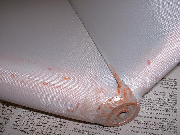
The first side gets covered (I don't like the "clam-shell" approach, I'd rather do each piece individually). | 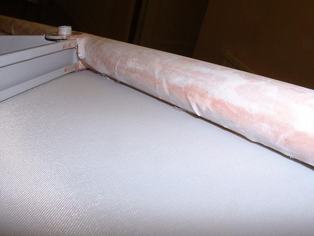 |
Notice how far round the tube the fabric is glued. |
 |
The curved edge is formed using a 250F iron whilst pulling the fabric to shape. | 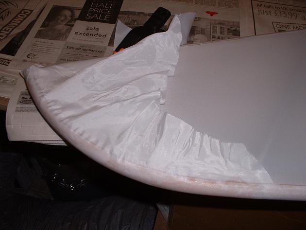 |
The fabric conforms to the bow, ready to be trimmed then glued... | 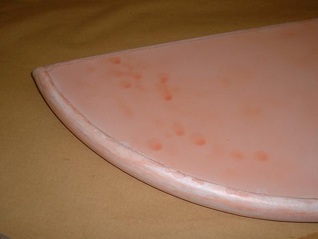 |
...and after pink goo-ing, here is the result. |
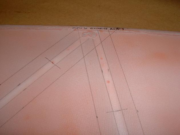 |
Marking out where the stitches and trim tapes will go. I will be using 4" spacing for the stitches... |  |
...and the fabric is stitched on. |
 |
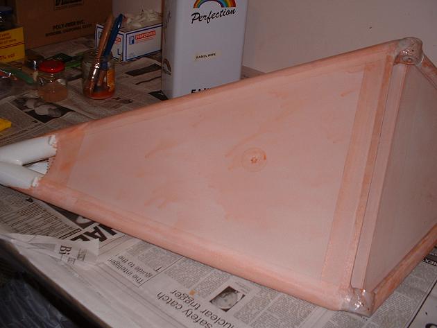
After taping, smoothing and applying the last brush-coat of pink goo, the finished stabilisers are ready for spraying. |
 |
All my drain grommets are the aluminium type. |
 |
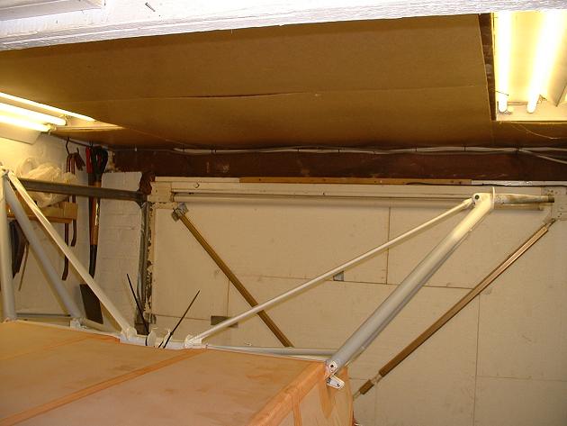
While the wings and fuselage are away for rigging (and my garage is empty) I take the opportunity of the extra space to spray up the tailfeathers.... |
 |
...and after the white for the stabilisers, I need to revisit the fuselage... | 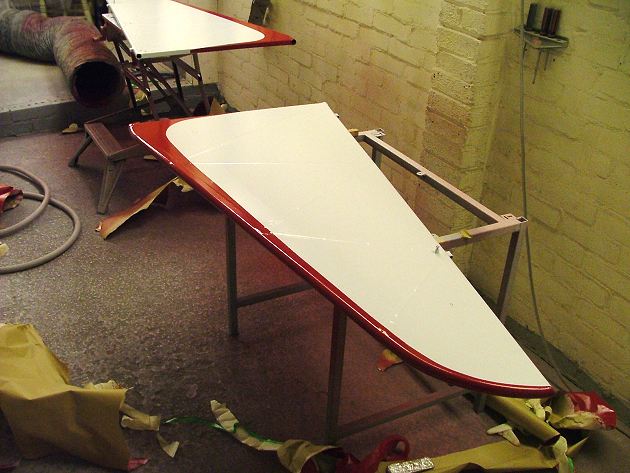 |
...to get the red trim aligned with the fin trim lines. |
 |
The fabric support wire was bowed, but was straightened by cutting one end and re-welding. |
 |
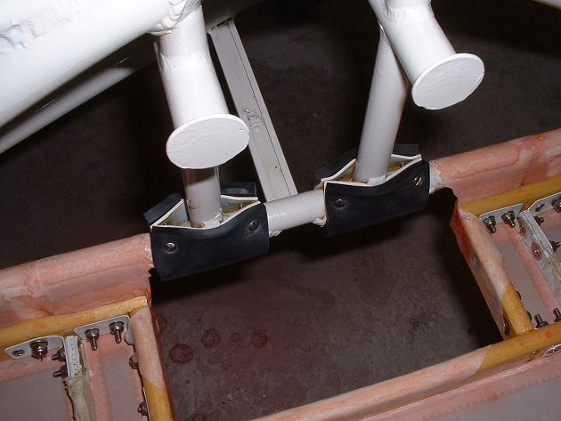 |
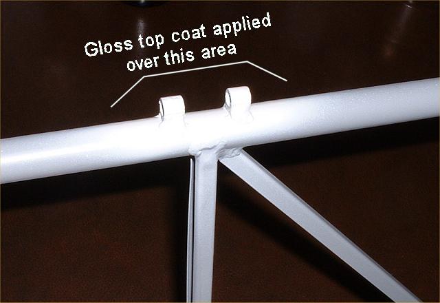
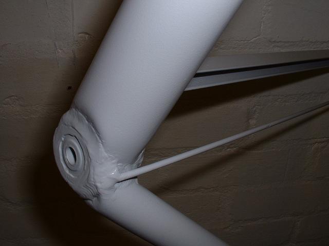
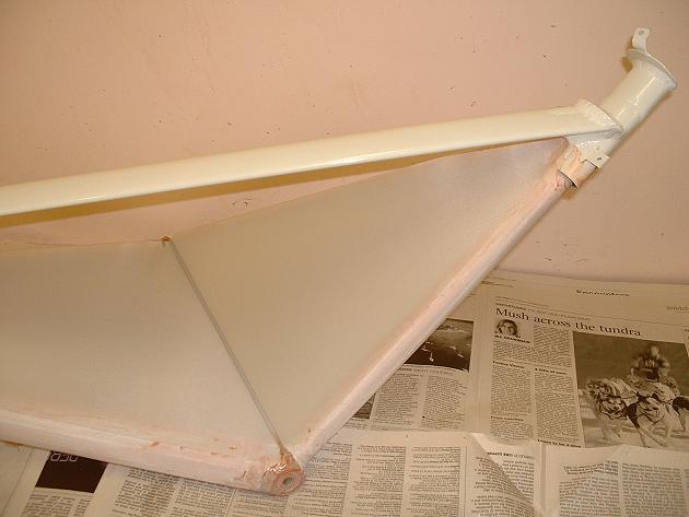
The gear is temporarily put on to ensure that
there is no interference with my fabric, and to position the gear bumpers for screwing on. Note in the left hand photo that the exposed areas have been gloss-coated in white. |
 |
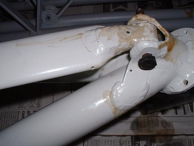 |
The undercarriage, stabilisers, elevators and
rudder, after the paint has cured, are internally sealed. A messy but necessary
task. Note again the gloss top coat. The left photo shows the reinstallation of corks to seal the stabilisers, well, any old excuse to have a bottle of the red! |
 |
 |
Undercarriage is covered. The only matters of note here are that the fabric for the "inside" of the gear goes under the wire... |
 |
 |
...and I use a pinch stitch to taughten the
fabric between the vees. This will stop the paint cracking down the
vertical legs due to drumming from the propeller slipstream. There is about a 3/4" gap between the two fabric surfaces. I have not bothered to cover the upper surface that you see under the seat...save weight where you can. |
Fuselage structural work
Fuselage Fabric
Wing Structural work
Wing Fabric
Ailerons
Cowls
Tailfeathers & Gear Legs
Doors Control Column & Panel
Final Assembly