


Ailerons
|
|
The ailerons themselves are in fair shape...a bit of crushing on the attachment points, so new spars to be made. |
|
|
I designed a drilling jig to get all the aileron spar holes in the right place. Sample piece of wood shows correct alignment. |
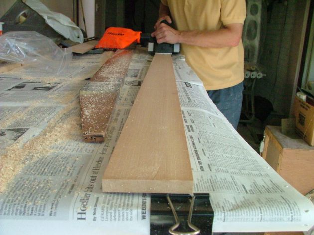 |
Planing the new aileron spars. I modified a cheap electric hand planer with longer blades to do the cut in one width. |
 |
I made a mess of measuring up the old spars, so
my new replacements need a lamination to get to the correct depth. Doh! One can never have too many G-cramps. |
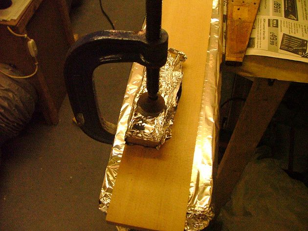 |
Using aluminium foil as a wrap-around of the timber load-bearing blocks when clamping up glued surfaces, prevents the glue sticking to the blocks. |
 |
I am using aluminium reinforcing plates
(0.080") on the new aileron spars instead of plywood. Floating anchor nuts will be used to permit any tightening of the bolts from the front of the spars, eliminating the need for cutting a hole in the aileron fabric to get a spanner on the nut. Using floating anchor nuts will ensure correct alignment of the bolts. The aluminium plates will be glued on, in order to eliminate the wood splitting with age around the bolt holes. |
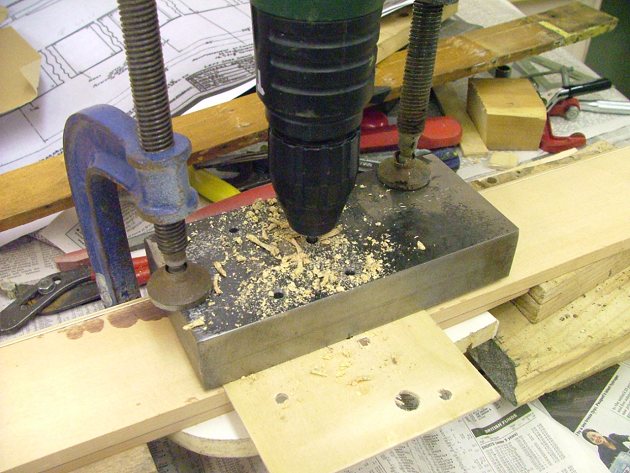 |
I can now drill the 3/16" holes in the
aileron spar using my jig. The depth of the jig allows me to free-hand the drilling; the
jig itself ensures alignment. Some of the L2 drawings (on CD) were very useful in getting the correct dimensions of the spar. |
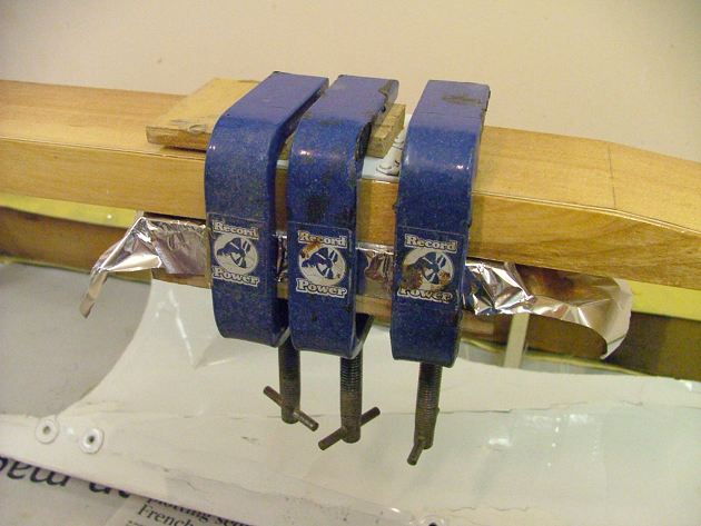 |
The centre reinforcing plates are attached.
I am using a structural two-part adhesive. The purpose of the adhesive is not
to ensure attachment (the clamping of the through-bolts does this), but rather to bond the
wood to prevent longitudinal splitting of the spar where the holes pass through. I
also drilled 1 mm (0.040") diameter holes through the plates and nail through these
holes as per the drawing. Note the use of tin foil to prevent the adhesive sticking to the wood backing piece. |
 |
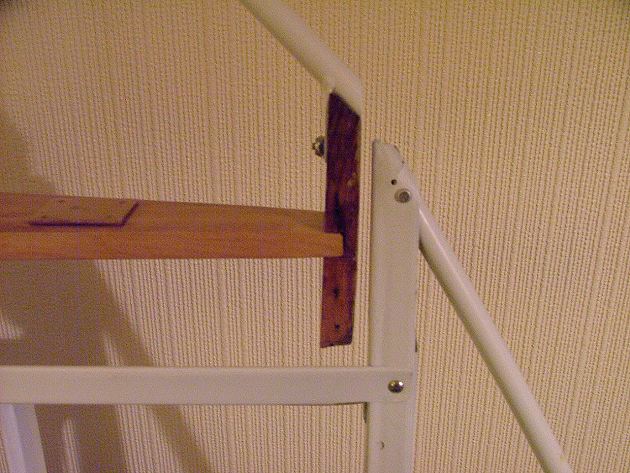
After varnishing, I temporarily mount the spar to the wing brackets (to make sure it'll fit!) |
 |
 |
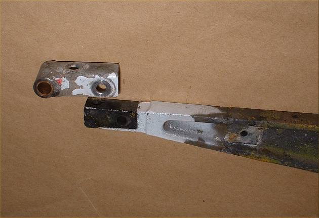
The magnesium aileron brackets are removed and
disassembled for inspection. These can be prone to dissimilar metal corrosion
between the magnesium and the steel end fittings. The right-hand photo shows removal of the oilite bushings, using the same drift as used on the tailfeather bushings. |
 |
Wing aileron bracket after bead blasting.... | 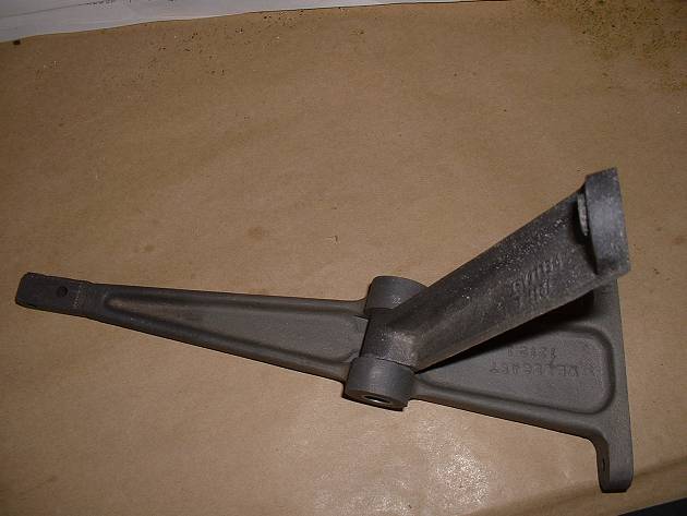 |
...and after Magna-Dyning. Next step is etch-prime and then epoxy prime. | 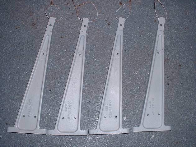 |
The four other aileron brackets |
 |
Here is the result for the inboard bracket on
the rear wing spar(1). Note also: (2) I have not yet completed the final trammelling and lock-nut tightening on the drag wires (3) The aileron brackets still need attaching to the aileron cove with little angles. |
 |
 |
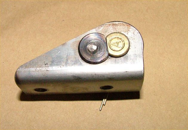 |
My friend David manufactured new aileron
brackets for me...and a jig to press them and drill them accurately. A spot-welded piece on one side will prevent rotation of the pin in service. Thanks, David, your skills and patience are very much appreciated. |
 |
I found it important to identify which rib came from which location, to ensure that the screw holes match up between the metal parts. |
 |
 |
 |
After gluing on and nailing the outer two attachment plates (after the ribs are slid on), another "dry run" ensures the trailing edge lines up. I have increased the spar length by 1/4" each end to reduce the enormous gap between the wing and the aileron ends. |
 |
The inboard end of the aileron gets a rib
reinforcing piece to prevent bowing under the fabric tension loads. This is a
one-piece "Vee-section" aluminium brace, countersunk riveted on to the aileron
butt rib AFTER the butt rib was nailed onto the spar. Remember the round aluminium tubing used on the wing braces? Well, I cut the corroded ends off the wing Dahlstrom pieces and re-used them in the ailerons. |
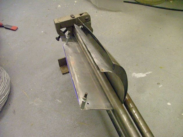 |
I use my slip rolls to create a new tip leading edge. The old one is Cleco'd to the new to get the right contour. |
 |
Spraying of the two aileron progresses well through the "pink goo" stage until... |
 |
...during the first coat of silver, I drop the one of the ailerons on to the tip bow. Ho-hum, repair required. |
 |
Repairs complete, the ailerons (& gear legs) get further sanding coats, and then the white treatment... |
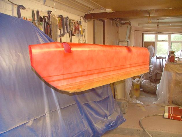 |
...and after masking, a dust coat of red. [Note the original aileron skin on the floor, used to get the same masking tape positions] |
 |
A couple of wet coats see the ailerons in full two-tone colour. |
Fuselage structural work
Fuselage Fabric
Wing Structural work
Wing Fabric
Ailerons
Cowls
Tailfeathers & Gear Legs
Doors Control Column & Panel
Final Assembly