My Taylorcraft
restoration project, G-BREY
by Robert Lees
Wing Structural
Work
Fuel
Tanks
Port Wing
Starboard Wing
Other
Fuel Tanks:
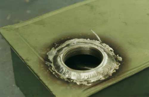
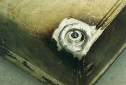
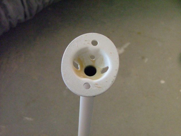
| New threaded fittings (for filler neck, outlet and fuel drain) are welded
in: |
 |
 |
 |
Reinforcing plates are welded at the same
time to spread the load when connecting up. Filler neck screws in, I didn't like the
glued-in original. |
 |
All tanks are leak-tested after
welding in new fittings. Also tests condoms. Pumped up, remained up for 24
hours, only wish I could say the same! One of four tanks leaked at a hairline crack
on one weld, I used gas-fitter's spray to find source of leak. Interestingly, all
the condoms never leaked or burst.
Inflation was through Schraeder valve connected into fuel drain hole. |
Port Wing:
 |
|
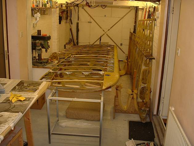
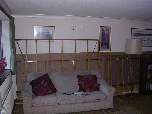
The wings are delivered to my house. |
 |
It's a tight squeeze... |
 |
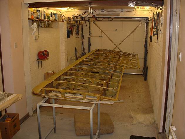
...but better after I relocate the other wing
to the living room. |
 |
 |
 |
I had previously removed the butt fittings
(front and rear spars) to inspect and measure them. Note in the left photo the
severe corrosion (painted over) on the rear fitting, so much so that someone decided to
add a doubler to take the loads. A real wasp's nest! |
 |
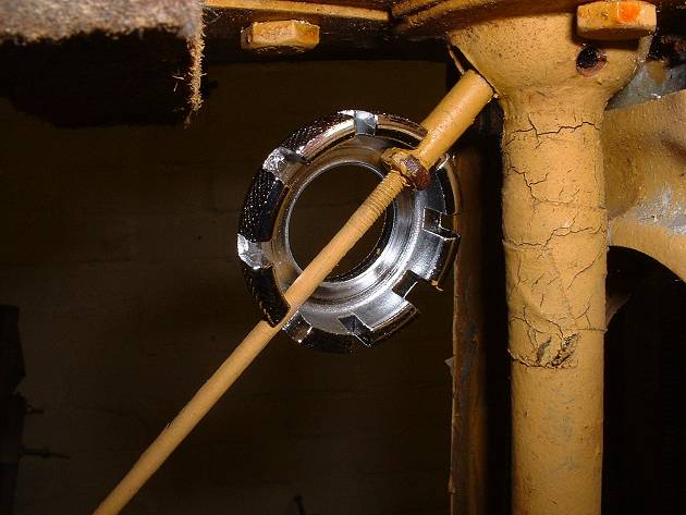
Using a cycle spoke key to undo the
wing bracing wires (No.10 slot seems to work great). |
 |
Removal of those pesky, corroded slotted screws
is simplified with the use of a small right-angled screwdriver, upon which pressure can be
borne to keep the blade from "camming out". I cleaned out the slot of each
screw beforehand with a mini hacksaw blade. |
 |
 |
The little fibre components inside the wing get
a clean-up...removal of decades of grime, paint and varnish; they turn out like new. |
 |
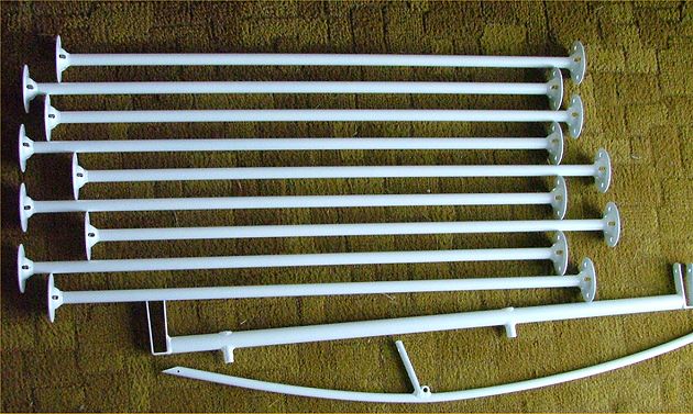
Some of the threaded end fittings of the wing
bracing wires are of different sizes....any explanations forthcoming? |
 |
..and the compression strut shims also show
minor differences.
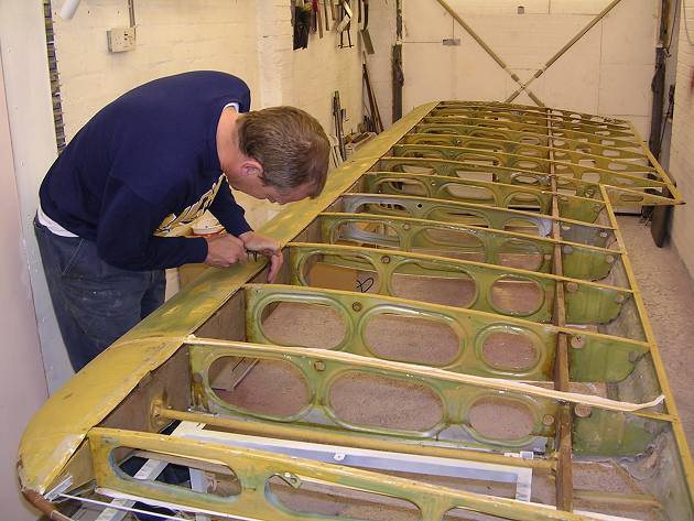
Port wing is S/No. 7352, stbd is 7284 (implying that the starboard wing is 78 units
earlier than the port wing. Airframe S/No is 7299. |
 |
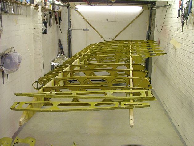
My rather Heath-Robinson but effective wing
rotating jig on the butt end of the wing. |
 |
One of the two laminations that make up the
front spar has a splice installed at the factory. |
 |
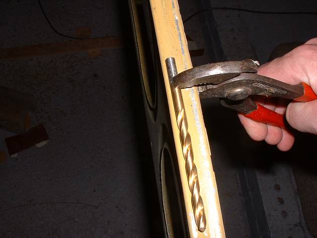
Some of the holes where the fabric wire goes
through the ribs are slightly deformed, so I use a suitably-sized drill bit to bring them
back to the contour of the rib cap.
The cap has a depression along its length, to permit the wire to lie level with the
upper surface of the rib. |
 |
The ribs get the acid-etch and clean-up
treatment... |
 |
...and some of the two-sided ribs I have to
fettle and reinforce where previous knocks have dented them. |
 |
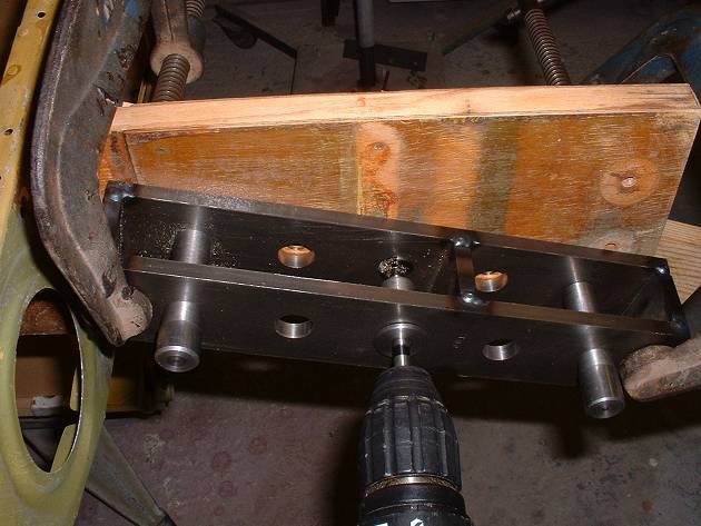
View of drill jig for opening out the existing
holes in the front spar. Using this jig, a hand-held drill can be used.
Behind the spar is a block of wood to drill into. The original bushings need
removing (pressing out with a drift) after alignment but before drilling.
Note that the root rib and first nose rib both need to be removed. |
 |
 |
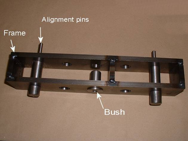
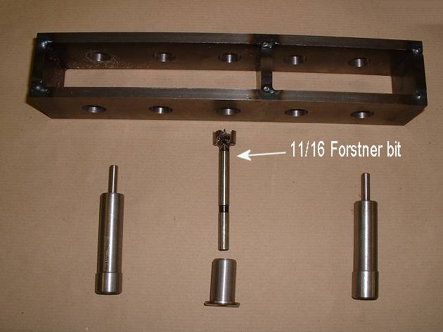
The frame has five jig-bored 11/16" holes
at the correct spacing.
The frame holds two 11/16" diameter locating pins
which fit inside the existing 1/4" holes. As each hole is drilled, the locating pin
can be pushed in to the drilled hole.
An 11/16" diameter bush holds the Forstner bit.
The pins and bush are interchangeable in each hole of the frame to permit each of
the five spar holes to be opened out. |
 |
Here's the result...five aligned and parallel
bores in which to glue new bushings. |
 |
This is the comparison in diameter between the
old bushings (on the left) and new ones (on the right) - same size bolts though... |
 |
..and this photo shows the new bushings
installed dry in the bores. |
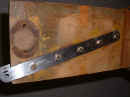 |
I glue the bushings in, but to ensure final
alignment while the glue dries, I bolt up the new butt fittings. These fittings were
manufactured on the same DRO Bridgeport as the drilling jig, so I am confident of the fit.
The straps were ground on their faces over full length to ensure that they will fit
between the ears on the fuselage. |
 |
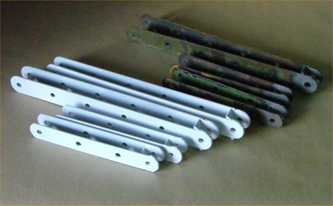
The new fittings for the rear spar; the
originals were severely corroded. |
 |
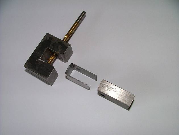
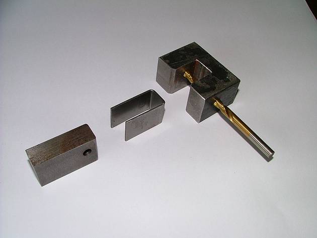
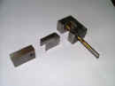
The end bracket is manufactured using a male
and female press die, with a drilling hole for the undersize hole (this to be reamed out
after welding). |
 |
 |
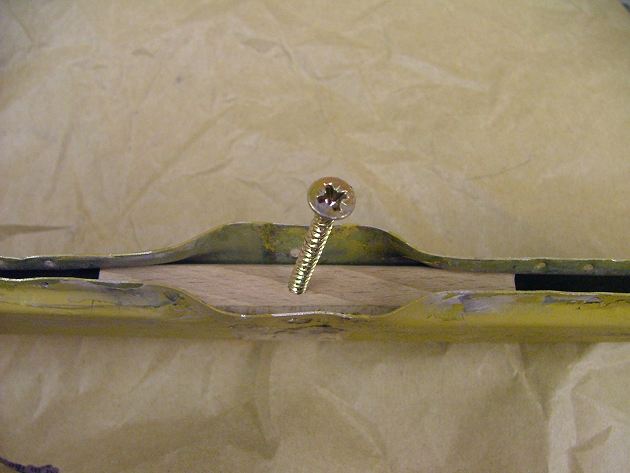
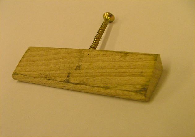
I use a wooden piece as a dummy spar to check
the assembly, which has an angled end. Note the pin used to ensure alignment of the
end hole... |
 |
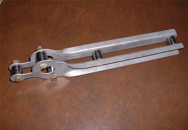
..and after welding & painting, here's the
result. |
 |
Spacers are used for the correct spacing of the
strut attachment brackets... |
 |
..and after welding of reinforcing plates. |
 |
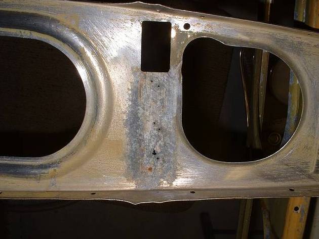
The butt ribs are severely corroded where they
butt up against the spars...requiring amputation of the cancerous bits...
[rectangular hole is aperture for spar butt fitting] |
 |
..and so needing some serious patches where
both front and rear spars meet the rib.
The reliance upon the Alclad to protect the material against moisture and wood acid
erosion was misplaced, perhaps in the light of what we know now.
Parts will be painted to protect them, before riveting together |
 |
More patches! |
 |
 |
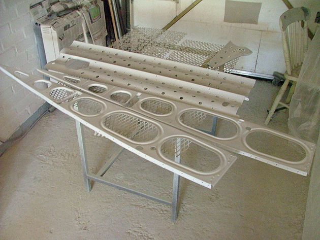
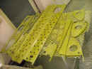
Various wing internal components are bead
blasted and painted... |
 |
...and after painting, the internal bores are
treated with oil to prevent corrosion. |
 |
More painting! |
 |
I completely de-riveted the aileron cove parts
(to get rid of more of those horrible steel rivets), and after cleaning up, re-fabricked
the inside of the cove. Flush solid rivets then installed in new holes to reattach
the stiffening edges. Pigeon Poo used during rivet installation (wet-riveting). |
 |
Previous problems with the last trailing edge
rib before the aileron bowing (because of fabric tension) will hopefully be resolved by
stiffening the rib with some 0.015" braces riveted on... |
 |
..and here is the result after screwing on the
other side of the rib, (braces fitted both top and bottom...space required between the two
braces for aileron cables). |
 |
Although I varnished all the holes through the
spars, you need to ream them out to fit the new bolts. Therefore there is always the risk
of the holes permitting bare wood and bare steel to come into contact (bad for corrosion).
So I use "Duralac" (Pigeon Poo) as a wet sealant immediately before
inserting the new bolts. |
 |
 |
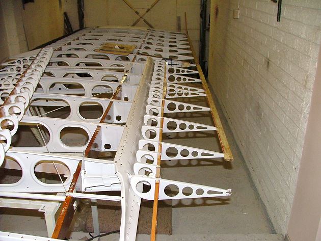
But wing reassembly is progressing!
(Drag wires go under anti-drag wires...but I am assembling inverted, so in my case,
they go the other way around).
Bare steel bolt heads will be wax-oiled for corrosion protection).
One of the compression struts is shorter than the rest; this goes at the strut
bracket fittings. |
 |
 |
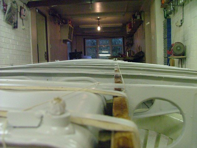
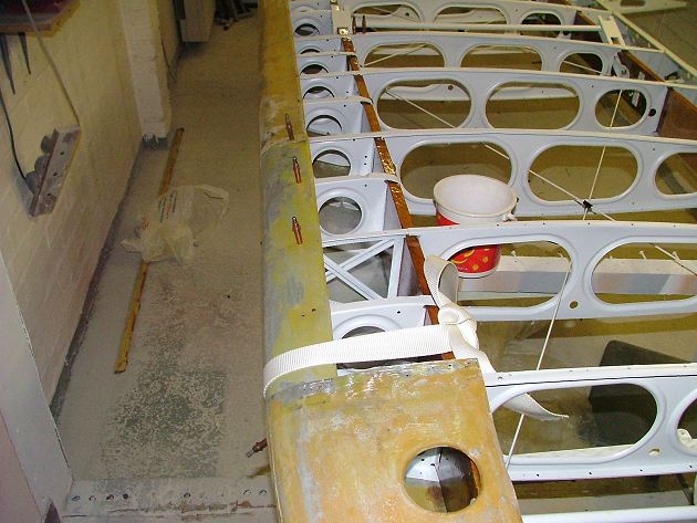
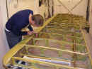
String lines assure the straightness of the
spars during trammelling. The right-hand photo shows the wing with a block inserted
under the front spar to simulate the wash-out to verify that nothing alters. |
 |
 |
The original Dahlstrom "C" section
used as bracing each end of the wing trailing edge were suffering a bit...so I am going to
replace them with stiffer and lighter aluminium tubing. Ali tubing annealed at the
ends using a light flame prior to bending/flattening. I used the more complete Dahlstrom pieces from the wing to make new ones for
the ailerons. |
 |
The leading and trailing edges undergo
necessary corrosion removal, repairs and fettling, prior to filling out the final few
dents with Poly-Fiber "Superfil". The blue slab is the wing, protected against
the up-and-coming overspray. |
 |
 |
Several iterations of paint/sand/fill,
paint/sand/fill were necessary. |
 |
So the port wing is structurally complete... |
 |
...well, almost. After turning over to
attach the underside of the leading edge, some more filling needed. |
Starboard wing;
no real news to report, other than the following:
 |
 |
As per the port, the starboard wing spars
were varnished, and then masked off for spraying of the ribs (here in etch-prime).
Those components removed for rework were also etch-primed.
Two-pack epoxy prime to follow. |
 |
During rebuild of the aileron spars, I first
ensure alignment of the old aileron spars to the new aileron brackets. Then I can be
sure that the new aileron spars, when drilled according to the drawing, will fit. |
 |
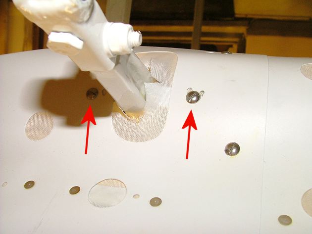
Note that the lower edge of the aileron cove
(this photo taken while the wing is upside down) has drain holes for the lower section.
These must be allowed to ventilate to atmosphere.
The aileron cove was rid of the pesky steel rivets, and new flush rivets installed. |
 |
 |
Damage to the trailing edges of the wings and
ailerons is hammered out using a hardwood block, sanded to the correct contour.
Removal of rivets/staples holding the trailing edge is required, but with care, can be
reinstalled.
The final contour will be dressed with micro to get the proper shape. |
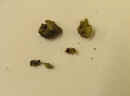 |
The trailing edge of the starboard wing
contained the remnants of wasps nests...probably from Texas in the late Eighties. |
 |
A trial re-fitting the leading edge. The
Cleco's fit rivet holes as found...there had evidently been previous damage to the wing
tip, necessitating replacement of the outboard leading edge. Note the truss rib
previously used as a replacement. This damage probably occurred in 1987, of
which I have heard anecdotal evidence, but no log book entry. |
 |
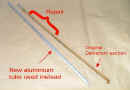
Some repair work required on the trailing edge
of the wing, due to corrosion of the original section. Note the round aluminium tube
used as bracing instead of the original Dahlstrom section. |
 |
After trammelling the wing, the starboard
aileron is jigged to the wing. I found it very valuable to do this while both the
wing and aileron were uncovered, since some shimming of the magnesium brackets (on the
wing rear spar) and of the aileron trailing edge were required to get the best alignment.
Note that I only dismantled the starboard aileron after rebuilding the port, so
that for both, I would have a pattern to work from. |
 |
After final aileron jiggering and pokering, I
can secure the magnesium brackets to the cove. |
Other:
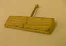
 |
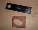
While I am in the riveting mood, I rivet up the
inspection covers.
This was another case of me hating those pesky steel rivets that manufacturers seem
to love...
...so I de-riveted the lot and started again. It was an ideal time to
bead-blast the steel spring & paint it front and back, separate from the aluminium
cover. |
 |
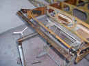
The wings and fuselage are
delivered to the airport to check the spar spacing and rigging. Both wings and
fuselage having undergone some major surgery, I was unwilling to take the risk of the
wings not fitting. It would be a lot easier to make any adjustments before covering.
I do not have the space at home to do this. |
 |
 |
In fact, with the help of many friends, the
wings almost fell on, with no further adjustment or trammelling required. The
diagonals (sternpost to wingtips) came out within ±
¼", so I was happy |
Taylorcraft.org.uk Home
Fuselage structural work
Fuselage Fabric
Wing Structural work
Wing Fabric
Ailerons
Cowls
Tailfeathers & Gear Legs
Doors Control Column & Panel
Final Assembly
Other
restoration photos
Tools used